English
 français
 Deutsch
 Español
 italiano
 русский
 português
 中文
中文
×
A packaging machine operation station. With the line idle, you touch anywhere on the screen and it responds. The moment the sealing and cutting mechanism moves and the servo and VFD pick up load, the screen starts "moving on its own" — phantom touches appear where nobody is touching, and the button the operator actually presses does nothing. Stop the machine and everything is fine again. The first instinct of the machine builder is usually "the panel is bad." Swap in another unit of the same model, and the problem stays.
This pattern is typical, and it tells you something: touch accuracy was never the screen's problem alone.
The same panel will register tens of thousands of taps on an office desk without an error, yet on the machine it misbehaves within days. Between the two sits the whole chain of supply, grounding, routing, mechanical mounting, the medium on the surface, and the software above it.
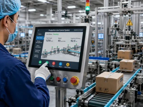
The difference is not "a bit dirtier." It changes the physical conditions that touch detection relies on.
Dust, oil, and water film. A projected-capacitive panel reads a touch from the tiny change in coupling capacitance between sensor layers, and a finger is not the only thing that perturbs that field.
Oil mist and cutting fluid leave a film with a dielectric constant, which slowly raises or lowers the baseline; if the film is uneven, you get one patch that phantom-touches at random and another patch that no amount of pressing will register.
Water film is worse — water conducts, and it bridges several sensor nodes, so the controller sees one large, oddly shaped "touch." Self-capacitance designs are especially sensitive to this, which is why most water-rejection schemes are built on mutual-capacitance architecture.
Dry dust alone is minor; the problem is when it absorbs moisture and effectively becomes a local water film. And worth saying: wiping the screen with an oily rag smears point contamination into one continuous film, and the symptom gets visibly worse.
Temperature and humidity. The controller tracks the baseline to cancel slow environmental drift; what breaks it is usually the rate of change, not the absolute value.
A terminal rolled from a cold store into ambient, or an operation station whose cabinet has not warmed up yet on a winter startup, will have a baseline that cannot keep up — "not quite right for the first ten minutes after power-on, then fine."
If it gets less accurate the longer it runs, check the backlight and cabinet cooling instead. There is another trap: if something is resting on the screen at power-on — a hand, a layer of condensation, a wrench left on top — the controller folds it into the initial baseline, and that area stays "dead" until the next power cycle. It is easily mistaken for local physical damage.
Electromagnetic interference. The PWM output of a VFD or servo drive has a steep dv/dt, which generates broadband common-mode noise.
Part of it enters the controller through the supply and ground; part is radiated and coupled into the sensor layer — which, being a flat plane full of conductor traces, is a decent receiving antenna by nature.
When the noise reaches the same order as the real signal, the controller has only two moves: report false touches (phantom), or raise the threshold and filter out the noise along with the real touches (dropouts, sluggishness). If touch anomalies track the running state of high-power equipment exactly — bad under load, fine when stopped — suspect EMI, grounding, and routing first. Do not swap the panel yet. Conversely, if the panel drifts even with the machine fully stopped and only the panel powered, then it is time to suspect the panel itself or its supply.
Mechanical vibration. Capacitive sensing does not depend on pressure, so vibration mainly causes three things: long-term fretting wear at the flex connector, raising contact resistance — which shows up as intermittent total loss of response (lightly flexing the harness or tapping the enclosure reproduces it, and that is almost certainly a connection issue); hand jitter that enlarges the landing point, so small buttons get mis-hit — that is an interface-design problem; and panel deformation under load. Resistive panels are a separate case: vibration plus constant pressure accelerates wear of the conductive layer.
Gloves. A glove adds a layer of dielectric and increases the distance, so the capacitance change drops sharply. To make gloved operation work you must raise the gain or lower the threshold — and both moves make the panel more sensitive to noise and contamination.
That is the on-site contradiction: you raise sensitivity so workers in safety gloves can operate it, and then the moment a wash-down wets the surface it phantom-touches wildly.
A proper industrial scheme offers switchable modes — glove, normal, water — toggled through an HMI setting or a DO signal from the PLC. Asking "does it support gloves" at spec time is nearly useless; ask how thick, what material, how much water rejection survives after switching to glove mode, and whether the switch can be triggered by an external signal.
Surface wear. A resistive panel is a consumable. After a button is pressed hundreds of thousands of times at the same spot, the ITO layer degrades locally, showing as fixed-position dead zones or drift.
When the floor report says "only the 'Start' button is hard to press now, everything else is fine," that is essentially confirmed; the cheapest fix is a revised screen layout that moves the high-frequency button.
For capacitive panels, the AF oleophobic coating wears off under cleaners and abrasive particles, and then oil and water no longer bead and roll off but spread into a film — "started mis-touching after two years of use" is sometimes a coating problem, not an electronics problem.
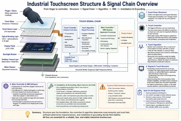
The touch panel itself. The thicker the cover glass, the more the finger signal attenuates. "How thick a glove it penetrates" and "how hard an impact it survives" pull against each other; you cannot optimize one in isolation.
The touch controller. This is where the biggest, most overlooked differences live. The same sensor glass with different controllers can differ by an order of magnitude in noise immunity.
What has engineering meaning is the signal-to-noise ratio, and whether it has scan-frequency self-adaptation / hopping (to dodge the VFD interference band), multi-sample correlation judging, and automatic baseline rebuild.
The touch algorithm. This is what decides, under noise, water film, and gloves, "is this a real touch." One trade-off must be stated plainly: filtering strength and response latency are opposites — confirming a touch is real needs multiple frames, and more frames is more latency.
A scheme tuned very hard for noise immunity often feels slightly "dull," which you must think through in advance for applications sensitive to continuous dragging, like manual jogging or parameter fine-tuning sliders.
Display and touch structure. Air bonding is cheap but leaves an air gap: one, parallax, so an operator looking at an angle hits off — common on vertical operation stations, especially when the panel is mounted high or low; two, the gap can condense in temperature cycling.
Optical bonding reduces parallax, reads better in sunlight, and resists shock, at the cost of price and repairability; prefer it for high/low-temperature, outdoor, and off-axis viewing positions.
Host and HMI software. A fair share of "sluggish touch" is nowhere in the touch chain. If the HMI polls PLC comms, refreshes trend charts, and writes logs on the main thread, touch events have to queue — "fast normally, but unresponsive the moment an alarm pops or data refreshes." Build a blank test page with a few buttons and no background tasks. If the test page is fine but the real interface is sluggish, that is software, and swapping the panel changes nothing.
Mounting and grounding. This likely accounts for the largest share of field problems, and deserves its own section.
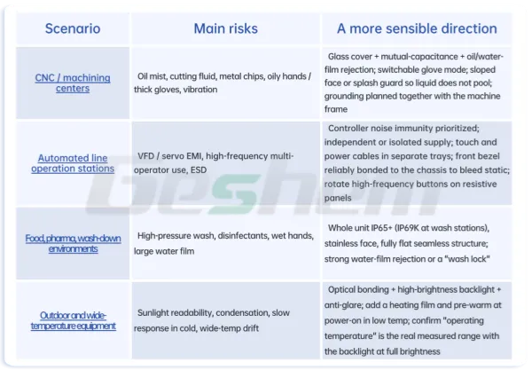
Two additions. In clean environments, an IP rating is not chemical compatibility: IEC 60529 defines protection against solid objects and water, not resistance to acid/alkali, solvents, or disinfectants.
Wiping repeatedly with chlorine-based disinfectant or alcohol, the coating, the seal, and the panel silk-screen each have their own tolerance limit. Low-temperature problems are often the LCD, not the touch: at low temperature the liquid crystal responds slowly and the image smears, so it looks like "no response when touched" while the touch point was already reported.
In that case heating beats changing the touch scheme.
Things that directly decide the touch experience:
The combination of touch technology and cover thickness — this sets glove adaptability, impact resistance, and the sensitivity ceiling. Looking at either one alone means nothing.
Controller noise immunity and mode support: does it have frequency hopping, can it switch glove / water modes, and can that switch be triggered by an external signal.
Response latency and report rate: report rate decides whether swiping is smooth; end-to-end latency decides the feel. Both get eaten partly by the HMI software on the real machine, so reading module specs alone makes you optimistic.
EMC immunity level, and whether the test object is the whole unit or just the module. A module-level claim and a whole-unit pass — with supply, enclosure, harness, and grounding included — are not the same thing at all. Read which of IEC 61000-4-2 (ESD), -4-3 (radiated immunity), -4-4 (EFT burst), -4-6 (conducted immunity) were tested, at what level, applied to which port.
Operating temperature range: confirm whether it is the operating temperature at full backlight brightness or just storage, and whether it is derated at the high end. This is the field most often overstated.
Things easily overlooked that will bite you on site:
Linearity at the edges and corners. Many panels are accurate in the center and clearly off at the four sides. The check is simple: draw a full-screen grid and walk a finger along the edge point by point, watching the deviation. Interfaces that place function buttons at the screen edge are hit hardest.
Grounding terminal design. Is there an independent, reliably crimped ground stud? Is the front bezel bonded to the chassis with low impedance (not just "resting against" a painted surface)? That decides whether ESD has a proper bleed path.
Vibration / shock test conditions. Were they done per IEC 60068-2-6 (sinusoidal vibration), IEC 60068-2-27 (shock), and at what magnitude and axis? Also look at the connector and harness fixing method — many vibration problems live there, not in the panel body.
Maintainability: can the panel be replaced on its own, how long is the spare-part cycle, can the firmware be upgraded on site.
Specs are measured under single-variable lab conditions; the field runs multiple factors at once. A panel rated for thick gloves and rated IP65 looks fine on paper; but if glove mode and water mode cannot be switched independently, under the combined duty of "gloved operation plus periodic wash-down" the two ratings fight each other.
You can only judge by breaking the process down and seeing what state the operator's hand is in at each step. Specifying is essentially matching duty to environment, not comparing parameter sizes.
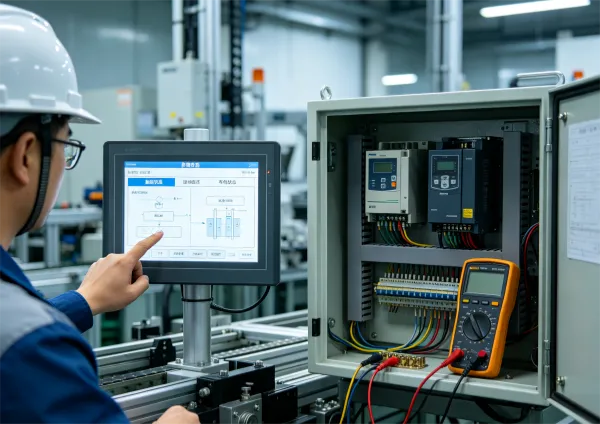
Grounding, highest priority. The controller measures capacitance change relative to its own reference ground. If the unit's ground "floats" relative to earth, or the PE connection impedance is high, that reference ground sways with the noise. One symptom confirms it directly: When the operator rests one hand on the equipment's metal frame the touch works, and the moment the hand leaves it goes dead or phantom-touches. See that and do not troubleshoot the panel — troubleshoot the ground.
In practice, run a separate wire of adequate cross-section from the unit's ground stud straight to the cabinet ground busbar; do not daisy-chain it behind other equipment, and do not "just ground it" through a mounting screw — paint, oxidation, and washers make the contact resistance uncontrollable.
Ground the shield at one end only; grounding both ends can form a ground loop and inject noise.
Supply, do not share it with inductive loads. Sharing 24 V with solenoid valves, contactors, and relay coils is the source of many intermittent faults. The coil's turn-off reverse spike leaves a transient on the supply, and the controller may reset or rebuild its baseline — "every time that cylinder actuates the screen flickers."
The check is direct: hang a scope on the panel's supply terminals, repeat that actuation a few times, and watch for dips and spikes. Fix it by giving the HMI its own supply branch with isolation or filtering, and by adding RC snubbers or freewheeling diodes across the inductive loads.
Routing. Touch, display, and comms cables do not share a tray with VFD output and servo power, and certainly do not run parallel over a long distance; when they must cross, cross as close to perpendicular as possible; keep harnesses short and away from drive heat sinks and output terminals.
In high-interference environments watch the length and shield quality of the USB touch cable, and switch to industrial shielded cable with ferrite cores if needed.
Mechanical mounting — force changes the touch behavior. A slightly small cutout, burrs or unevenness at the corners, and after tightening the sensor glass takes uneven stress, giving fixed-position local sensitivity anomalies.
Over-tightened clamps with uneven torque let the panel deform slightly; tightening diagonally and controlling torque beats "tighter is better." The front metal bezel must not press into the active sensing area, nor sit too close to the sensor layer, or the edge will be pulled off continuously.
Calibration and baseline. Resistive panels need multi-point calibration — redo it after swapping the panel, after disassembly, after changing the main board. Capacitive panels generally need no position calibration, but ensure the surface is clean, unpressed, and condensation-free at power-on.
During commissioning people often restart while pressing the screen, then complain about dead zones. Where possible, put "baseline rebuild" as a button in the maintenance menu for the floor staff.
Interface design offsets part of the hardware shortfall. Size buttons for a gloved contact area, not a bare fingertip; make the main action buttons on the order of 12–20 mm with clear gaps between them — that beats squeezing touch precision in the parameters. Do not put critical soft buttons at the screen edge, where linearity is worst.
Add a second confirmation or press-and-hold for hazardous actions; that is the most practical move against vibration and phantom touches. Then give feedback with press-to-change-color, a beep, or an action-confirmation readback — a lot of "dropout" complaints are really the feeling of no feedback, so the operator repeats the press and ends up triggering the action twice.
Ⅰ.Classify the symptom: global or local? Continuous or intermittent? Not registering, hitting the wrong position, or moving with nobody touching it? If you cannot classify it, everything after is guessing.
Ⅱ.Find the correlation: log which equipment is moving when the anomaly occurs. Tracks VFD / servo / high-power heating / welding / cylinder actuation exactly → go down the EMI / supply / grounding branch.
Ⅲ.Build a minimum system: disconnect comms, peripherals, and expansion I/O, leave only an independent supply, and observe while the equipment runs. If it is fine now, the problem is in the external chain, not the panel.
Ⅳ.Swap the supply: temporarily run it from a 24 V source unrelated to the equipment. If the symptom vanishes, go back and chase interference and dips on the original supply.
Ⅴ.Verify grounding: measure the resistance from the unit ground point to the ground busbar and confirm it is a dedicated lead; have the operator touch and release the equipment frame to see the difference; check whether the shield is grounded at both ends.
Ⅵ.Clean and rebuild baseline: thoroughly clean with a lint-free cloth and a compatible cleaner, then power on again with the surface dry and untouched.
Ⅶ.Check settings and firmware: is glove or water mode accidentally on, was sensitivity changed, is the firmware version the same as on the healthy units.
Ⅷ.Check software load: compare response speed on the blank test page to rule out HMI program blocking.
Ⅸ.Check mechanics and connections: does lightly flexing the harness or tapping the enclosure reproduce it; remove the bezel and inspect tightening torque, cutout flatness, and the connector for fretting wear or oxidation.
Ⅹ.Only now consider replacing the touch module or the whole unit — and after replacement, observe long enough. An intermittent fault "fixed for a few days after swapping" does not mean you found the cause.
The logic of this order: Rule out external conditions first, then mounting, then software, and only last suspect the hardware. Reverse it and the cost is high and the conclusion unreliable.
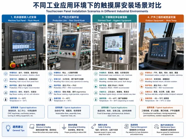
Back to that packaging machine at the start. Most of these problems in the end live neither in the panel's resolution nor in how advanced the touch technology is, but in whether the ground is a dedicated lead, whether the touch cable shared a tray with the servo power, whether 24 V was shared with the solenoids, and whether the interface buttons were drawn for a bare fingertip.
Accurate response of an industrial touch panel is the combined result of the touch panel, controller algorithm, structural process, environmental suitability, mounting and grounding, and the software above it. Pushing any single link to its limit cannot cover a shortfall elsewhere; a scheme whose specs are not flashy but is matched to the duty and mounted and grounded to standard will, on the floor, run far more stably than a panel with pretty specs installed carelessly.
So before specifying, state the duty clearly: what state the operator's hand is in when it touches the panel, what is interfering around it, whether there is a wash-down or disinfection step, how the temperature moves, how much vibration, and how many presses a day. Lay those out, then go to the parameter sheet, and the judgement gets much clearer.
Do not chase the highest single parameter — chase a touch scheme matched to the specific industrial environment.
Shenzhen Geshem Technology Co., Ltd. is a national high-tech enterprise with 14 years of deep industry experience, specializing in the R&D, design, intelligent manufacturing, and sales of industrial computers, industrial panel PCs, and rugged tablets; the company holds a total of 92 authorized patents (including 27 invention patents).